

This approach is taught in the analysis of say rectangular floor slabs where the applied design loads (dead loads plus design live loads) are split between two strips at right angles. The deflections at the cross over points are made equal to give the proportion of loads carried in each direction.
For simply supported square slabs the loads carried in each direction are equal but when the aspect ratio of the slab is more rectangular, the majority of the loads are carried by the short span. Aside - ridge/valley membrane systems normally carry most loads this way.
The adoption of the Finite Element Method (FEM) was relatively new in this area. My task essentially boiled down to how to assemble the large number of simultaneous equations representing the stiffness matrix K and to solve the fundamental equations P = KD for the displacements D caused by the applied loads P.
This is the famous Hooke's Law often illustrated by a one-dimensional spring - double the load, the deflection is doubled. K is the single number for the spring constant.
I was able to use the second largest computer in Canada which provided a user the grand amount of memory of 256 kilobytes to fit the program and all the generated information. 256 Kb is not even enough to store a low resolution photo! And that stiffness matrix was small at 1000 simultaneous equations (K could be 1000x1000 numbers - even single precision was 8 bytes per number so 8Mb or 32 times the memory available. I am told that in the 2020s, it is not uncommon to be looking at 1,000,000 simultaneous equations)
The specific dam was the Idukki Dam in India. It remains (2024) as the third highest in India (Asia?) at 169 metres. In comparison, the highest arched dam in Australia is the Gordon Dam on the Franklin River at 140 metres. The height of the Sydney Harbour Bridge is 134 metres.
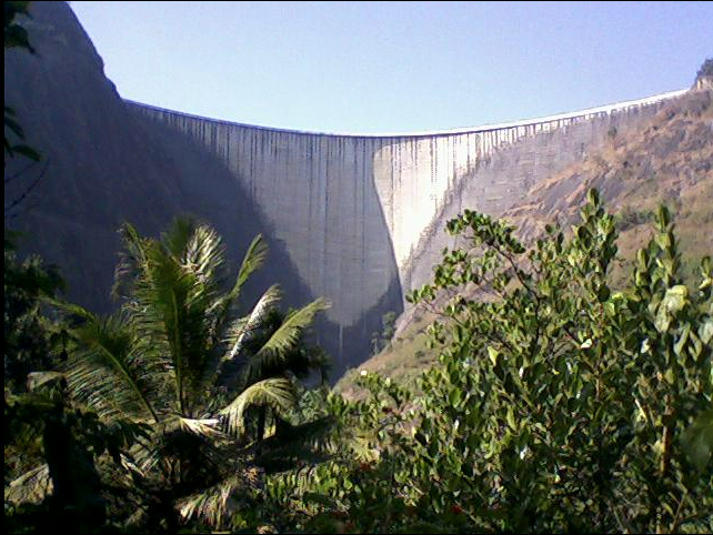
View of the Idukki Dam from downstream (source unknown)
 |
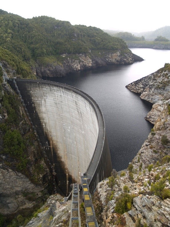 |
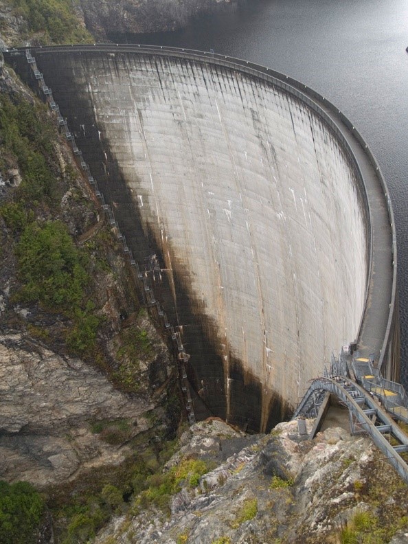
Views of the 140m high Gordon Dam in Tasmania (Brenton Kneen, 2008)
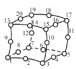
Defining the Double Curvature Shape – Brick Elements
For the arched dam 20 noded isoparametric “brick” elements were used to model the upstream and downstream surfaces. The (x,y,z) coordinates of the 20 nodes representing part of the arch dam were calculated or assumed. In the diagram, nodes 1,2,3,10,15,14,13 and 9 might represent the downstream face of the dam. In our study 26 different brick elements were used to model the complete dam.
Involvement with New Fabric Structures in Australia
Ivanhoe Girls Grammar School 1976
This small structure was my first involvement with David McCready and Bob Barrow who were Geodome Spaceframes. Located in Punt Road South Yarra, they had been building geodesic framed structures clad with fabric to cover domestic swimming pools. At the time (unsure, late 1975 or 1976 probably) they were incredibly enthusiastic and were like two machine guns firing all sorts of questions at me.
Many people acknowledge that this project was perhaps the first tension fabric structure in Australia. There may have been some pneumatic examples, but I am not aware of them. It was certainly my first fabric structure, and a lot was learnt from it. The Ivanhoe School had a kindergarten area (forgotten size, say 10x10m square) enclosed area with a fabric roof comprising four straight-sided hypars meeting at a raised central point. The hypars were numerically divided into a grid that could be triangulated. The cutting patterns were determined by “flattening out” a sequence of adjacent triangles. The flattened shape was drawn on the roll of fabric and the strips were made a bit narrower, and the overall length was reduced slightly to allow for stretch when the fabric was tightened.
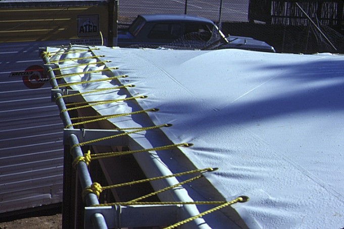
Some test results of the fabric load-elongation were available from the manufacturer in Germany, but we decided to use about half the strain values. To accommodate the unknowns, the external ends of the fabric were fitted with closely spaced eyelets which permitted a roped attachment to a steel pipe located a reasonable distance from the edge of the perimeter frame. A fabric flashing was welded to the underside of the stretched surface.
 |
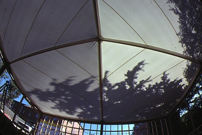 |
(Left). Considerable Range of Adjustment at Edges. Use of a corner curved bar to prevent water ponding. (Right) Internal View of 4 Hypar Fabric Roof.
 |
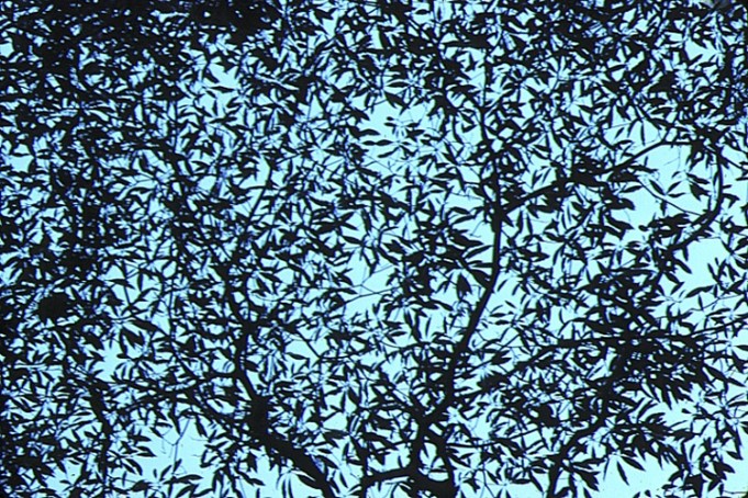 |
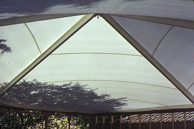
Internal Views. Leaf patterns on roof
Dean Park Sound Shell – Townsville 1978-80
Quite a few spaceframe projects were designed and built prior to the Dean Park Project.
The next fabric project was an enormous learning experience:
- The size of the structure was significantly larger,
- it was a different shape with curved edges with steel cables,
- the shape was not covered by the Australian Standards as far as being able to calculate wind loads.
- it was in an exposed location near the coast.
- it was in a cyclone area.
- I did not have any software for:
- Simulating the 3D shape
- Doing any form of structural analysis
- Producing the cutting patterns.
A 1:100 model had been developed by Geodome and accepted as the concept by the client. I believe a fixed price contract had been signed between Geodome and the Townsville Council (I think for about $64,000). Engineering fees might have been about $6-7,000. What did become apparent was that because of the unique structure that more time was needed to complete the project. I believe this was negotiated without penalty.
Some tensioned fabric structures had been built overseas and one engineering company (Gieger Berger) quoted $10,000 to do a “preliminary design”. Obviously, this would not be able to be accommodated in the fixed price contract, the outcome was to attempt to develop some software ASAP.
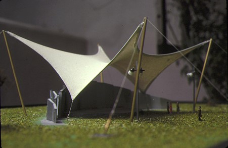
The Model showing sound reflecting concrete slabs and stage area
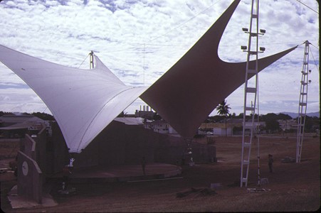
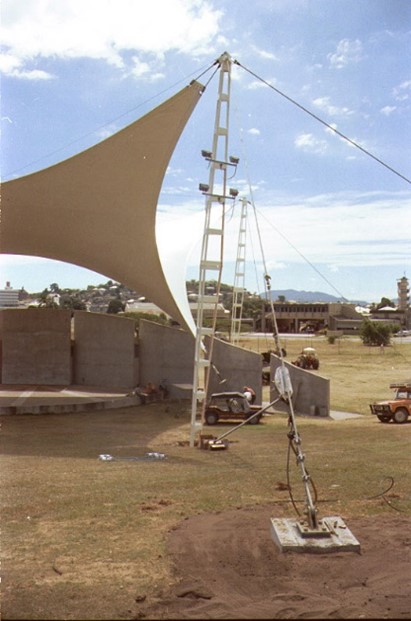
The completed project – cleanup incomplete
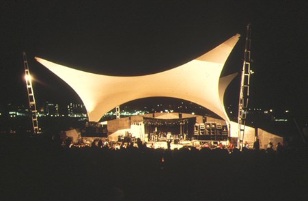
The completed project
Defining the Shape – back to the Arched Dams
From the 1:100 scale model it was possible to estimate some (x,y,z) coordinates of key points such as corner points of the fabric shell at the mast heads and tie down locations and at the mid points of the edge cables and the centre of the structure. Using a quarter of the structure the same “shape functions” as used for the Idukki arch dam work were employed but only for one face of the brick element.
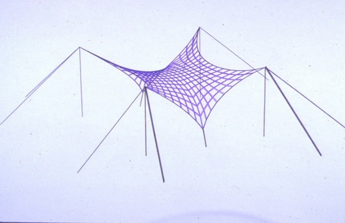
This quarter was sub-divided into a mesh and reflected two ways, then adding masts and guys to depict the entire structure.
 |
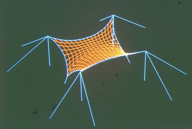 |
The Computer-Generated Trial 3D Shape using Shape Functions as adapted from the Arched Dam work.
With this shape there was no guarantee that the surface was smooth (Slope continuity) across the joins of the different quarters. The next stage was to produce some “model” cutting patterns. These patterns did not fit onto a scaled roll of fabric but were good enough that a more detailed 1:10 scale model of the quarter surface could be made. (By Geodome, no images available)
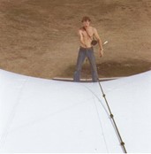
From this 1:10 model, mylar sheets were carefully laid and overlapped on the surface to represent the rolls of fabric. These were physically measured to provide the cutting patters. Aside from some localized wrinkles near clamping plates the vast majority of the 1000 sqm surface felt uniformly taut - yes we walked over as much as possible.
 |
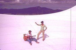 |
David McCready (Founding & Life Member of MSAA/LSAA) Walking off the Shell. Right: Client was happy!
Some Details
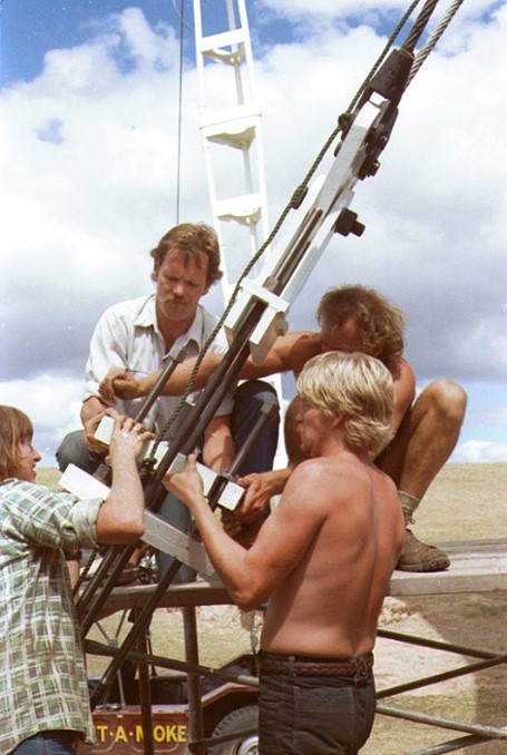
The four main masts were triangular in cross section with the corner tubes battened together giving some ability to climb the masts. In hindsight the “steps” were a bit far apart. A rubber pad under the base permitted the masts to be pivoted outwards if required to obtain a taut fabric surface. This was not needed. Likewise, the eight corner guy ropes were adjustable in length by about 600mm by using bulldog grips. Again, adjustments not needed.
 |
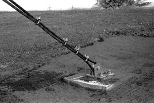 |
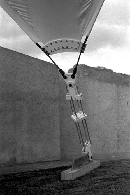
The two low points were connected to a large concrete anchor block which had a thick steel plate with several places that could be used to attach the tie down fitting. This was done to cater for any discrepancies in the geometric modelling or patterning. Whilst the computer software to perform a structural analysis under wind loads had not been completed, an approximate hand analysis suggested that a tie down force of 86 kN was required. We used a hydraulic jack to give the force. The fitting used long threaded high tensile rods that would enable a very large change in length to be achieved.
The first trial was to use the outermost attachment locations and after the 86 kN prestress force was reached everything “felt right” so nothing was changed, and we gathered on top of the stressed fabric shell and celebrated.
 |
 |
The Low Point Anchorage Detail showing Multiple Options for Adjustments. In the left photo the only localized fabric wrinkling was near the lower clamping plates.
Based on the experience at the Dean Park Sound Shell, most future anchorage points did not include the details to provide the same amount of adjustment.
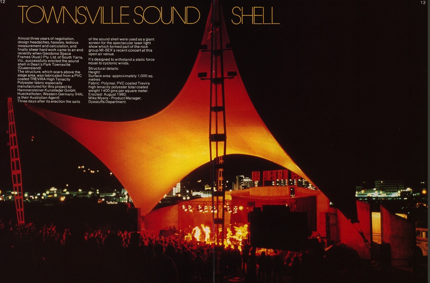
The Dean Park Soundshell exceeded all expectations in terms of its life and condition as a pioneering tensioned membrane structure in Australia.
I believe Jimmy Barnes and others performed there but some 24 years after completion - life expectancy for PVC coated polyester fabrics was considered good at 10 years back then - the area was redeveloped as a carpark. Townsville had by then a new Civic and Entertainment Centre which was opened in 1978 and has been a dynamic centre of entertainment and performing arts in the city - probably not for the likes of rock festivals however.
See these articles Sound Shell History or about the Civic Centre


