This project was entered into the LSAA 2009 Awards - Category 4 (4220)
Entrant: Ronstan – Contractors
Location: Barkley St, Footscray Vic Client: Western Bulldogs, Whitten Oval
Architect: Peddle Thorp Struct. Eng.: Irwin Consultants
Builder: Salta Fabricator: Ronstan
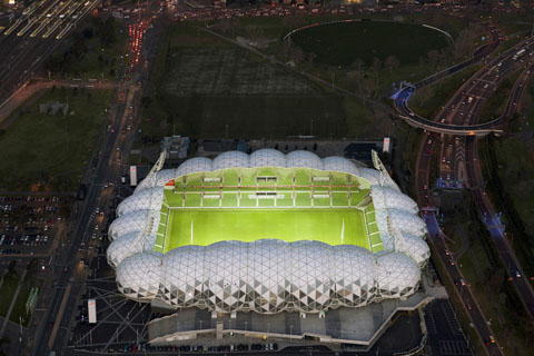
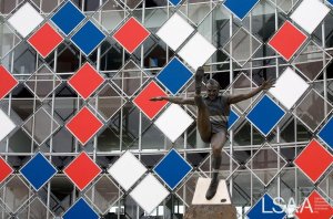
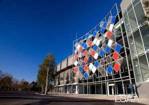
Design Brief: The Architect called for a transparent screening element that would act as a billboard for the oval as well as the local community. It needed to be light enough that it did not detract from the facade but provided adequate passive solar protection to enhance the sustainability of the building.


Structural Systems
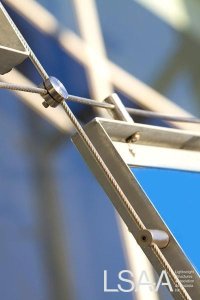
A rigid SHS steel frame is used as the anchor structure for the 8mm diameter cable net that spreads across the arc of the building façade. The steel is installed on concrete footings and tied back to the slabs of the building. The cables then connect via cleats around the boarder and utilize Ronstan ACS1 fittings passing through eyelets at each segment of the arc. The eyelets assist in preventing deflection by reducing the free span of the cables therefore limiting the amount of pre stress in the cables. To these cables lightweight panels of coloured metal sheet and mesh are attached using custom manufactured cable clamps.
The basic layout of the screens and cables was provided by the architect at a sketch level. Ronstan then liaised with the building and engineer to finalise the detailing. It is in this period that our experience and knowledge became invaluable to the project team.
We started by rationalizing the sizing of the pattern matching the size of the panels with our details and the overall size of the façade. This had the effect of removing any one off details in the cable clamps, panels or cable connection points having a drastic effect on the economics both in terms of material/fabrication along with erection time.
Materials
Mild Steel galvanized SHS posts – Used to reflect the blue collar area the oval resides in
Grade 316 stainless steel cables and fittings – Stainless steel presented the best load to size ratio for the tensile members allowing us to utlise an 8mm diameter
Panels – These were made from galvanized equal angel sections with Vitrapanels infill panels in the team colours along with perforated mesh panels.
Fabrication
Typical End Details:
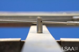
This project features 30 individual cables crossing each other at angle of 45 degrees to the vertical. Each cable was fabricated from Ø8mm wire and included a compact adjuster at either end. Compact Adjusters (Figure 1) have been developed specifically for architectural projects and include a unique telescoping mechanism which provides a useful level of adjustment without the presence of bulky turnbuckles.
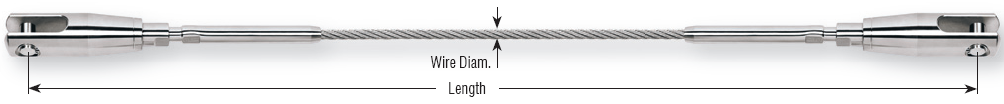
Figure1 : Typical Compact Adjuster Ronstan Turn buckles
Each end of each cable is connected to a mild steel cleat on the steelwork. These cleats were detailed, supplied and installed by others to a detail compatible with Ronstan’s compact adjusters. To prevent galvanic corrosion between the mild steel attachment cleats and the stainless steel cables, isolation bushes and washers are installed into each cleat prior to the installation of the cables.
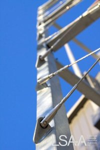
Intermediate cable supports:
Where each individual cable crosses a column, cables passed through custom made stainless steel gr 316 intermediate cable clamps to deflect the cables around the curve of the façade. A through bolted connection is provided in steelwork at each clamp location (by others) to allow attachment of the cable clamp.
By deflecting the cables at each column, all cables in between any two given columns would remain in approximately the same plane.
Façade panels:
Each panel came with a galvanised steel angle frame and galvanised steel flat bar clamping plates to clamp and hold the infill material. Surface finishes on the frame and clamp plates are ‘as galvanised.’
Panel infill materials consist of stainless steel gr304 stainless steel woven mesh and vitrapanels in accordance to Peddle thorp drawings. Each panel was attached to the cable net using stainless steel cross clamps similar to those fixing the cable to the steelwork. Clamps were secured in place using stainless steel grub screws.
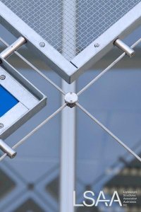
Cross clamps:
At each location where cables cross over each other, Ø40mm adjustable stainless steel cross clamps are provided to bind the net elements together and prevent adjacent cables rubbing against each other.
Tensioning during installation:
As part of the installation process the tension in each cable was measured and to compare those measurements against a schedule provided by the structural engineer. This was to ensure that the initial tension in the cable is with acceptable limits and that the structure is neither under tensioned, nor over tensioned.
Construction and Maintenance
Method:
A. Installation of cables
- Start with rear cable
- Check the orientation, arrangement, sequence of clamps and compact adjuster of each cables
- Ensure all clamps are secured on cable by fastening the grub screw on each clamp (Note that grub screw should be firm but not over tight). Use masking tapes / cable ties to reinforce the last clamps of each cable.
- Remove the clevis pin from compact adjusters keep in a clean box or bag for later use.
- Raise cable to its cleat and install compact adjuster (with adjustment 2/3 open) to its cleat. (Note that all threads must be cleaned and Tef-jel to be applied just before installation. Isolation bush and isolation rings are installed
- Installation of column clamps to the correct column locations from top to bottom in accordance to The grub screws should not be tighten at this stage, ie, cable should be able to move across the column clamps freely.
- Repeat step 1 to 6 until all rear cables are in place.
- Start with front cables
- Repeat step to 6 until all front cables are in place.
- Swage the bottom end of each cable (at 2/3 open adjustment) and installed compact adjusted to the bottom cleat. Note that cable should be loose at this stage.
- Installation of cross clamps to every cable intersection. The grub screws should not be tighten at this stage, ie, cable should be able to move across the column clamps freely.
B. Installation of panels.
- Raise panel to its correct location
- Adjust the panel into position.
- Install panel to panel clamps (panel clamps are already attached to cables) by fastening button head socket screws from the inside of panel frame to panel clamps. (Ensure isolation rings are installed both side of the galv angles).
- Drive grub screws into panel clamps. The grub screws should not be tighten at this stage, ie, cable should be able to move across the column clamps freely.
Cable Tensioning
- The tension device provided has been calibrated using a known force for 8mm diameter cables.
- Read instruction manual of PT-3 Tension Measuring Device before operating this device.
- Attach PT-3 on the cable as per instruction.
- Each Cable should be progressively tension (max. tension allowable is 1000kg or 10kN as consult’s design advice.)
- Adjust clamps and panels if necessary.
- Repeat 4 to 5 until panels are evenly spaced.
- Tighten all clamps’ screws along cables.
Final Tension Check for Cables
- The tension device provided has been calibrated using a known force for 8mm diameter cables.
- Read instruction manual of PT-3 Tension Measuring Device before operating this device.
- Attach PT-3 on the tight cable as per instruction.
- The measurement results on the gauge show the tractive force on the cable shall be recorded in a log book before moving on to the next testing location.
- Convert the tractive force to cable tension force by referring to the calibration chart attached on the gauge.
- Submit results to engineer for record upon completion.
Monitoring and inspecting cable structures
6 monthly check - Visual inspection
- Check all end fixings that pins are secured & untouched.
- Check all turnbuckle lock nuts are secure & locked in position.
- Check all toggle ends (if used) are clear to articulate.
- Check surface of cable & end fittings is clean & free of any contaminants which may cause discolouration or staining of wire or end fittings. Clean with mild detergent & water if required
12 monthly check
- Check as per 6 monthly check.
- Check all pin connections are secured & free of wear.
- Clean all cable & end fitting surfaces of dirt & contaminants with mild detergent & water.
- Inspect all cable end swage fittings for any signs of stranding, overloading or damage to surfaces. Report & replace any suspect items.
- Check cables are still tensioned. This can be done simply by gripping each cable at its mid span and applying load perpendicular to the façade. Under this load the cable tension should feel firm.
- Check all bolts / nuts in the system are secure.
Costs
Project value approx $132,000